Constrained Least-Squares Linear Phase (CLSLP) FIR Filter Synthesis Algorithm
CLSLP Software Download at the End of Page — Press Here to Jump
Outline
-
Introduction
-
CLSLP (Constrained Least-Squares Linear Phase) is not a universal acronym and is used here as a local convenience and as the name of the associated software library
-
CLSLP is a minimum weighted least-squares technique for the efficient generation of linear-phase FIR filter and beamformer coefficients
-
The CLSLP filter synthesis algorithm is a computationally efficient operation that often allows for designs with real-time dynamic or adaptive filters in (1-20 ms on a PC)
-
Target filter response is specified by multiple frequency-interval definitions specifying the desired amplitude response
-
Any number of filter segments can be specified up to the memory limits of the host processor
-
Each statement is employed in filter synthesis as it is added to the cumulative square error
-
Four standard line interval types are provided: LinAbs, LinRel, ExpAbs, AbsRel
-
Interval start and stop amplitudes are specified as well as a auxiliary weight factor (default 1)
-
The CLSLP algorithm synthesizes the filter coefficient that minimizes the weighted square error
-
-
The FIR Filter phase is assumed linear by default so is not specified in the filter-segment definitions
-
Linear-phase filters have a constant time delay of (N-1)/2 samples where N is number of filter coefficients
-
Conjugate-Symmetric, Conjugate-Asymmetric, and Hybrid-Symmetry FIR filter coefficient synthesis patterns available
-
Phase slope is constant in CLSLP so that the sample delay is exactly (N-1)/2 samples (aka Linear Phase)
-
Constant phase offsets can be applied to all of the coefficients so as to generate Conjugate-Symmetric, Conjugate-Asymmetric, and Hybrid-Symmetry FIR filter coefficient phase types with exactly the same amplitude response
-
These are computationally efficient operations that amount to multiplying each filter coefficient by a constant complex value of unit magnitude
-
-
The GenerateFilter() member function has an optional third parameter RotAngRad, rotation angle in radians, which sets the constant phase offset (assumed 0 by default)
-
This constant phase offset, if specified, is periodic with period π
-
If the third parameter is omitted, a conjugate-symmetric coefficient pattern is generated by default (RotAngRad=0)
-
Conjugate-Symmetric Coefficient Pattern: RotAngRad = 0 + kπ (for any integer k)
-
Conjugate-Asymmetric Coefficient Pattern: RotAngRad = (π/2) + kπ (for any integer k)
-
Hybrid-Symmetry Coefficient Patterns: RotAngRad is a real value between 0 and π (+kπ) but not conjugate-symmetric nor conjugate-asymmetric (e.g. RotAngRad = 0.5 is Hybrid-Symmetric)
-
-
-
-
CLSLP software distribution and installation
-
The CLSLP download is at the end of this web page and distributed in zip-file form
-
CLSLP software is written to the C++20 standard and should run efficiently on any platform or (major) operating system that ports C++. Certainly Linux (GCC) and MS Windows. SIMD is also use if the platform supports it for runtime builds (-O3 on Linux).
-
The GSL math library is needed by CLSLP for real-time operation though this is a fairly standard library and easy to install
-
Additionally, the following libraries are used in the code examples below: GSL Math Library, FFTW, and GNUPLOT (plotting only)
-
-
The CLSLP algorithm synthesizes real or complex-valued linear-phase FIR filters
-
Real-valued filter frequencies are specified in the 0 to .5 Normalized Hz (NHz) range as -.5 to 0 is symmetric in amplitude (phase is linear by assumption)
-
Complex-valued filter frequencies are specified in the 0 to 1 Normalized Hz (NHz) range
-
Computationally efficient filter synthesis
-
e.g., A 501-coeffcient real-valued linear-phase FIR filter synthesized in 1.65 ms on standard desktop PC (-O3 Linux)
-
-
-
Filter interval definitions: Add() for complex-valued coefficient filters and AddSymmetric() for real-valued coefficient filters
-
For example: Filt.Add( CLSLP::eLin_AbsErr, 0, 1, 0, 0, 1e-16 )
-
First parameter is the amplitude segment type
-
eLin_AbsErr: Filter amplitude response is modeled as a linear segment, a straight line on a non-log amplitude graph.
-
eLin_RelErr: Filter amplitude response is modeled as a linear segment, a straight line on a non-log amplitude graph, with relative-error measure employed. With relative-error measure, you divide the square-error by the design amplitude squared. This approach sometimes improves the design of heavily-sloped amplitude responses as it normalizes the error evenly from high to low amplitudes. NOTE: Amplitudes cannot be 0 with relative-amplitude error measure as this would be division by zero!
-
eExp_AbsErr: Filter amplitude response is modeled as a exponential segment, a straight line on a log (dB) amplitude plot.
-
eExp_RelErr: Filter amplitude response is modeled as a exponential segment, a straight line on a log (dB) amplitude plot, with relative error measure employed. With relative error measure, you divide the square-error by the design amplitude squared. This approach sometimes improves the design of heavily-sloped amplitude responses as it normalizes the error so that lower-amplitude segments have a reasonable fit. NOTE: Amplitudes cannot be 0 with relative-amplitude error measure as this would be division by zero!
-
-
Parameters 2 and 3 are the starting and ending interval frequencies (mod 1.) in NHz. Best to keep these in the -1 to 1 range though any should work as they end up multiplied by 2π in trigonometric functions during synthesis.
-
Parameters 4 and 5 are the starting and ending filter interval amplitudes. NOTE: Design amplitudes of 0 are acceptable for non-relative (absolute) modes ONLY.
-
Parameter 6 is an auxiliary weight that multiplies the calculated square error of this interval (1 is default). If omitted in the C++ software it is assumed equal to 1. A value of 0 will caused the rule to be ignored in optimization.
-
-
Command AddSymmetric( xx, aa, bb, yy, zz, tt ) used to define a real-filter frequency interval is the same as the following two statements
-
Add( xx, aa, bb, yy, zz, tt )
-
Add( xx, 1.-bb, 1.-aa, zz, yy, tt )
-
-
NOTE: A common mistake in using the CLSLP algorithm is leaving frequency intervals undefined. The CLSLP algorithm is fast though at the expense of not testing for errors such as undefined frequency intervals. A safe workaround for this problem is to add a statement such as the one below (in red) to your list of filter segments. This will draw all frequency intervals toward zero with a low weight making zero the default value. Since this default rule has a low weight it will be overwhelmed in the optimization by the non-default rule. If portions of the frequency band are left undefined, the matrix equations cannot be solved uniquely. A false flag is returned from GenerateFilter() if their is not a unique solution.
-
Filt.Add( CLSLP::eLin_AbsErr, 0, 1, 0, 0, 1e-16 ); // Amplitudes to zero, with low weight, as default
-
-
Beamforming with CLSLP
-
Note that Example 1 below is a real-valued coefficient FIR filter whereas Examples 2 and 3 are complex-valued coefficient FIR filters
-
Real-Valued coefficient filter amplitude responses are symmetric about 0 NHz
-
The basic idea is to map Normalized Hz [-0.5,0.5] in frequency to [-MaxAngle,+MaxAngle] in angle-space by adjusting the inter-element spacing 'e'
-
A zero angle is on boresight or a line perpendicular to the line of array elements
-
The array weights (coefficients) and then synthesized using CLSLP
-
The Nyquist constraint, applied to beamforming, is a constraint on the maximum inter-element antenna spacing (Emax) as a function of the desired maximum off-boresight beam steering angle (ThetaMax): Emax = | 1 / ( 2 * sin(ThetaMax) ) |
-
Parameters and Variables
-
Wavelength 'λ'
-
Inter-element spacing 'e' in wavelengths 'λ'
-
's' is the number of extra wavelengths between the samples of adjacent antenna elements in wavelengths 'λ'
-
The inter-element Nyquist rate constraint is then: Emax = | 1 / ( 2 * sin(ThetaMax) ) |
-
The off-boresight beam steering angle in wavelengths is given by: sin(ThetaObs) = (s*λ) / (e*λ) = s / e
-
Design Example: Antenna with -45 to +45 degree azimuth scan within the Nyquist rate. What is the maximum inter-element spacing 'e'.
-
Emax = 1 / ( 2 * sin(ThetaMax) ) ===> Emax = | 1 / ( 2 * sin(π/4) ) | ===> 0.707 wavelengths λ / max element spacing 'e'
-
Create a thin rectangular passband filter with CLSLP centered at the desired NHz that corresponds to the desired look angle
-
Use CLSLP to generate a filter (array coefficients) where the number of coefficients is the same as the number of array elements
-
-
The CLSLP algorithm is fast enough so that filter/beam synthesis can usually be done in real-time operation (< 5 ms computation)
-
Introduction
The Constrained Least-Squares Linear-Phase (CLSLP) FIR Filter algorithm is a computationally efficient filter synthesis technique distributed here in the form of C++ source code. CLSLP is not a universal acronym and is used here as the name of the associated software package and as a convenient moniker in general. CLSLP LPFIR (Linear-Phase FIR) filters are, as the name implies, linear phase. This means that CLSLP phase response is a constant time delay of (N-1)/2 samples where N is the number of filter coefficients. It's easy to show that cascaded linear-phase FIR filters are themselves linear phase so this quality is preserved even in arbitrarily large filtering networks when this discipline is employed. With the inherent speed of the CLSLP Filter Synthesis Algorithm exotic processing schemes such as adaptive filtering systems are practical even on modest processing platforms.
Examples of CLSLP Algorithm Use
The following software snippets should illustrate use of this software by example. This download includes a full source-code build and test in subdirectory CLSLP/ as well as source-code builds for the examples used in the documentation. This code, as it's written in C++20, should run on most major operating systems. Additionally, if the CPU supports the SIMD instruction set, then the release mode (-O3) build should employ it if possible.
Example 1
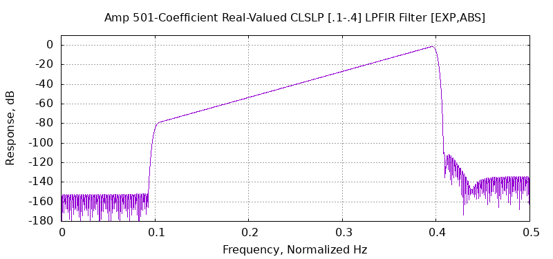
Example 1 is a 501-coefficient, real-valued, linear-phase FIR (LPFIR) filter synthesized by CLSLP in 1.50 ms, or about 2.99 μS/coef, on a standard desktop PC. The C++ commands used to synthesize this real-valued CLSLP filter are
#include "CLSLP.h"
CLSLP Filt;
Filt.SetGain(1);
// Optional Call. Gain is set to '1' by default. All
amplitudes multiplied by this quantity.
// AddSymmetric is for Real-Valued Filter Coefficients ([0,.5] mod
1.) Normalized Hz
// Add
is for Complex-Valued Filter Coefficients ([0,1.) mod 1.) Normalized
Hz
// Type
F0 F1 A0 A1 AuxMult
Filt.AddSymmetric( CLSLP::eLin_AbsErr, .0, .1,
0.00, 0.00, 1
);
Filt.AddSymmetric( CLSLP::eExp_AbsErr, .1, .4,
1e-4, 1.00, 1
);
Filt.AddSymmetric( CLSLP::eLin_AbsErr, .4, .5,
0.00, 0.00, 1
);
// A common reason why a filter solution cannot be determined is
that the frequency interval from 0 to 1 is not
// completely covered by the optimization statements
(above). This can be inconvenient during development
// so a simple work around is to add the following
statement to your code.
This statement draws all frequencies
// to zero in with a low weight as
default.
Filt.Add(
CLSLP::eLin_AbsErr, 0.00, 1.00, 0.00, 0.00, 1e-16 );
// Calculate the FIR Filter Coefficientsvector<complex<double>>
OutCoefs(501);
// The real-valued filter
coefficients are the real part of OutCoefs below. The imaginary
parts should be near zero.
vector<complex<double>>
OutCoefs(501);
const bool Valid = Filt.GenerateFilter( 501,
OutCoefs ); // 'Valid'
flag true if valid solution found
The amplitude response of this filter is

Example 2
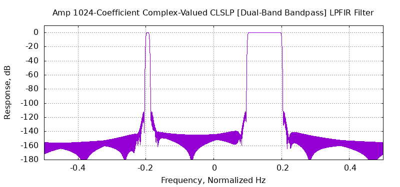
Example 2 is a 1024-coefficient, complex-valued, linear-phase FIR (LPFIR) filter synthesized by CLSLP in 6.28 ms, or about 6.13 μS/coef, on a standard desktop PC. The C++ commands used to synthesize this CLSLP filter are
#include "CLSLP.h"
CLSLP Filt;
Filt.SetGain(1);
// Optional Call. Gain is set to '1' by default. All
amplitudes multiplied by this quantity.
// AddSymmetric is for Real-Valued Filter Coefficients ([0,.5] mod
1.) Normalized Hz
// Add
is for Complex-Valued Filter Coefficients ([0,1.) mod 1.) Normalized
Hz
//
Type F0 F1
A0 A1 AuxMult
Filt.Add( CLSLP::eExp_AbsErr, -0.50, -0.20, 0.00, 0.00, 1 );
Filt.Add( CLSLP::eExp_AbsErr, -0.20, -0.19, 1.00, 1.00, 1 );
Filt.Add( CLSLP::eExp_AbsErr, -0.19, 0.10, 0.00, 0.00, 1 );
Filt.Add( CLSLP::eExp_AbsErr , 0.10, 0.20, 1.00, 1.00, 1 );
Filt.Add( CLSLP::eExp_AbsErr, 0.20, 0.40, 0.00,
0.00, 1 );
Filt.Add( CLSLP::eExp_AbsErr, 0.40, 0.50, 0.00,
0.00, 1 );
// A common reason why a filter solution cannot be determined is
that the frequency interval from 0 to 1 is not
// completely covered by the optimization statements
(above). This can be inconvenient during development
// so a simple work around is to add the following
statement to your code.
This statement draws all frequencies
// to zero in with a low weight
as default.
Filt.Add(
CLSLP::eLin_AbsErr, 0.00, 1.00, 0.00, 0.00, 1e-16 );
// Calculate the FIR Filter Coefficients
vector<complex<double>>
OutCoefs(1024);
// The real-valued filter
coefficients are the real part of OutCoefs below. The imaginary
parts should be near zero.
const bool Valid = Filt.GenerateFilter(
1024, OutCoefs );
// 'Valid' flag true if valid solution found
The amplitude response of this filter is

Example 3
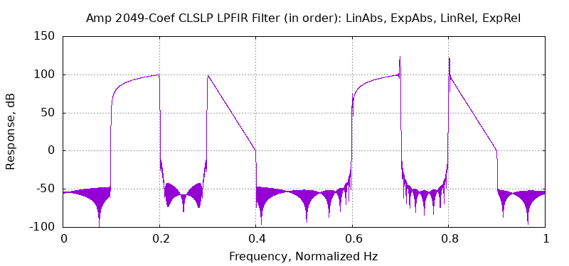
Example 3 is a 2049-coefficient, complex-valued, linear-phase FIR (LPFIR) filter synthesized by CLSLP in 27.07 ms, or about 13.21 μS/coef, on a standard desktop PC. The C++ commands used to synthesize this CLSLP filter are
#include "CLSLP.h"
CLSLP Filt;
Filt.SetGain(1);
// Optional Call. Gain is set to '1' by default. All
amplitudes multiplied by this quantity.
// AddSymmetric is for Real-Valued Filter Coefficients ([0,.5]
mod 1.) Normalized Hz
// Add
is for Complex-Valued Filter Coefficients ([0,1.) mod 1.)
Normalized Hz
//
Type F0
F1 A0 A1 AuxMult
Filt.Add( CLSLP::eLin_AbsErr, 0.00, 0.10, 0.00, 0.00, 1 );
Filt.Add( CLSLP::eLin_AbsErr, 0.10, 0.20, 1.00, 1e5, 1 );
Filt.Add( CLSLP::eLin_AbsErr, 0.20, 0.30, 0.00, 0.00, 1 );
Filt.Add( CLSLP::eExp_AbsErr, 0.30, 0.40, 1e5, 1.00, 1 );
Filt.Add( CLSLP::eLin_AbsErr, 0.40, 0.50, 0.00, 0.00, 1 );
Filt.Add( CLSLP::eLin_AbsErr, 0.50, 0.60, 0.00, 0.00, 1 );
Filt.Add( CLSLP::eLin_RelErr, 0.60, 0.70, 1.00, 1e5,
1 );
Filt.Add( CLSLP::eLin_AbsErr, 0.70, 0.80, 0.00, 0.00, 1 );
Filt.Add( CLSLP::eExp_RelErr, 0.80, 0.90, 1e5, 1.00,
1 );
Filt.Add( CLSLP::eLin_AbsErr, 0.90, 1.00, 0.00, 0.00, 1 );
// A common reason why a filter solution cannot be determined is
that the frequency interval from 0 to 1 is not
// completely covered by the optimization statements
(above). This can be inconvenient during development
// so a simple work around is to add the following
statement to your code.
This statement draws all frequencies
// to zero in with a low weight
as default.
Filt.Add(
CLSLP::eLin_AbsErr, 0.00, 1.00, 0.00, 0.00, 1e-16 );
// Calculate the FIR Filter Coefficients
vector<complex<double>>
OutCoefs(2049);
// The real-valued filter
coefficients are the real part of OutCoefs below. The imaginary
parts should be near zero.
bool Valid = Filt.GenerateFilter( 2049, OutCoefs );
// 'Valid' flag true if valid solution found
The amplitude response of this filter is

Undefined Frequency intervals
A common mistake using the CLSLP algorithm is leaving frequency intervals undefined. The entire frequency interval from 0 to 1 NHz (Normalized Hertz) must be specified in order to get a unique (valid) filter solution. If AddSymmetric() commands are used, it is only necessary to completely define 0 to .5 NHz as symmerty about 0 NHz is assumed. It's fine to define frequency intervals multiple times. Unusually one definition will have a larger weight therefore will take precedence in the coefficient solution. The default command in the next paragraph is an excellent example. If any frequency interval is undefined, the amplitude will tend to zero with a error weight factor of 1e-16 (see example in next paragraph). Any other specific interval definition will take precedence as it will have a normal weight of 1 (default) thus dominating the optimization.
The CLSLP algorithm is fast though at the expense of testing for errors such as undefined frequency intervals. A safe workaround for this problem is to add a statement such as the one below to your list of filter segments.
This will draw all frequency intervals toward zero with a low weight making zero the default amplitude value.
CLSLP Software Download
The zip file below contains a sample filter synthesis example as well as all the source code to embed CLSLP in your own design. This software is written in the C++20 language and should run on any major operating system (new C++ feature). A standard CMAKE build scheme is used. Sample Linux command files are included if you need a refresher on CMAKE builds. This download should have everything you need to embed this algorithm for your own application. All this code is released on a Standard BSD 3-Clause License.
Source Code, CMAKE Build, and Utility Linux Scripts — No Binary Files
C++20 standard code so software should build run on most major operating systems as per the language standard
Any Questions email at WEJC@WEJC.COM
The Original Asilomar Paper on CLSLP Algorithm [most math detail]
During the conversion of the MATLAB code to C++, an error was made in converting the indices from MATLAB's 1-based to the C++ 0-based numbering. Change n to (n-1) in example equations (30), (33), (37), (39), (41), and (43).
Additional Documentation
Documentation for CLSLP is provided in either of the two documents below. The first file is a basic PDF file describing the algorithm in general in general terms
CLSLP FIR Filter Synthesis.pdf
This second document contains the same information as the first document plus additional material: the published paper on the technique (math details), annotated C++ listings, as well as filter synthesis examples
CLSLP FIR Filter Synthesis Software and Docs.pdf